
For this post about the electronics, I’m going to cover everything including the joysticks, buttons, all the wiring, the power in general and just how everything works. I really don’t have too much experience with electrical wiring etc but my neighbour is an electrician so it was great to be able to run some questions past him when required. I pretty much had worked it all out myself though, so you don’t need to have an electrician neighbour. I just like getting the confirmation to put my mind at ease.
First of all here is a very crude sketch I made, just to get my head around how each of the electronic parts was going to link up inside the cabinet.

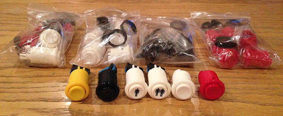
Buttons
As discussed in my Decisions post, the buttons that I got were a combination of leaf switch (for the 6 main game buttons per player) and micro switch buttons for the operational buttons such as Player 1 and Insert Coin etc. These were all purchased from Arcade World UK. If you cut your holes with a 28mm spade bit these screw in really easily. You just take off the black ring, drop the button into the hole and screw the ring back on. The leaf buttons are really easy but the micro switch buttons are slightly more cumbersome as they have the actual microswitch device that you have to slot into them. You do have to be aware of the depth you require for these buttons and make sure they’re not going to hit anything, especially if, like me, you have buttons on the bottom of the control panel too, as they could hit the buttons come down from the top if the depth of your control panel isn’t sufficient. Luckily mine worked out ok and there was space for all the button parts on the inside of the control panel.
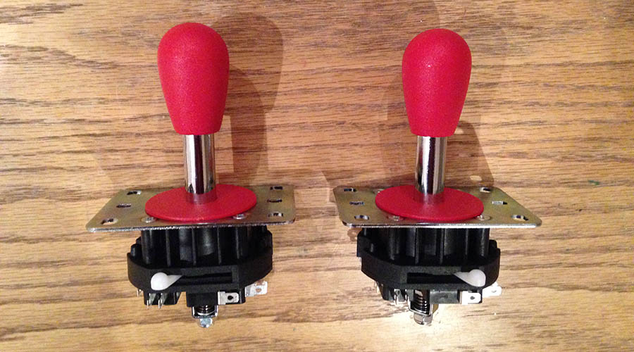
Joysticks
I chose to go for the Mag Stik Plus joystick which is switchable from 4-way to 8-way. I got them from Arcade World UK too. There were no instructions or anything with them but I managed to look online and find an exploded diagram of how to mount the joysticks. You just unscrew the main bolt and then slide bits off, put the main shaft in the hole in the control panel from above and then put the bottom back on from underneath and reattach all the pieces. Not too hard to mount to be honest. The biggest problem was the routing of the hole beforehand and also how to keep it secure once it was in. You can see how I did this again in the Building the Control Panel post.
Controller interface
This is the board that tells the computer what buttons are being pressed. I went for the i-Pac 2 from Ultimarc. Basically it has a bunch of terminals that each represent a keyboard press. These keyboard presses are assigned to a MAME command such as Up, Down, Fire, Insert Coin etc, and you just have to wire up each button to the corresponding terminal on the controller board. No soldering or anything required as you just put the open wire into the terminal and screw down the little screw. Easy peasy.
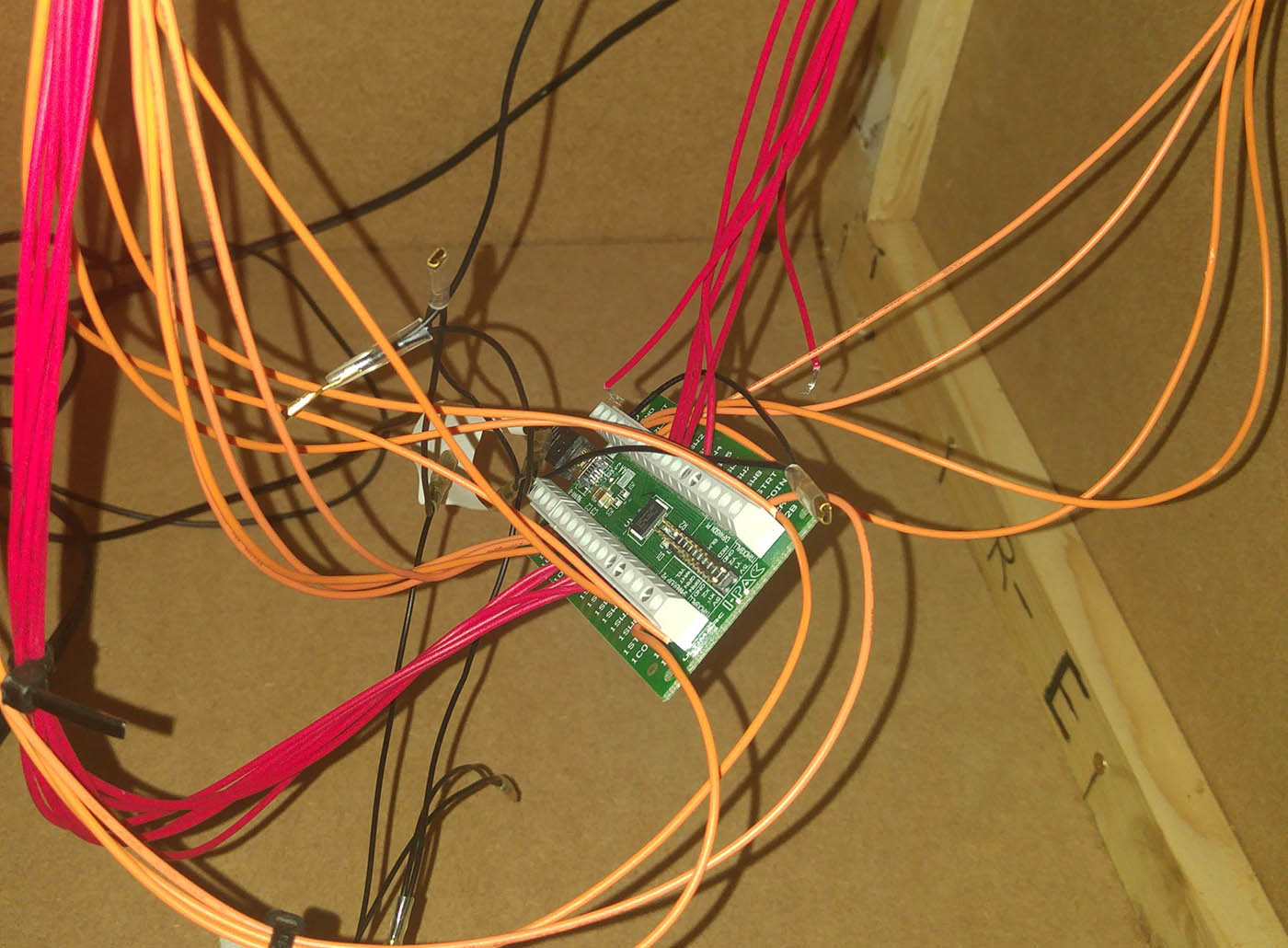
Wiring the controls
Next up you have to wire up all the controls. This can get really fiddly but I actually really enjoyed it and found it therapeutic. You just have to start by making sure you have wires with the right spade connectors. If all your buttons are micro switches then it’s easy as you will only need the large connectors. But some of mine, the leaf switches, had smaller terminals and so needed wires with smaller spade connectors. I knew this in advance and bought both sets of wires from Arcade World UK. You then have to attach all the wires from the buttons to the controller board. I’ll start with the Ground as that’s the most complicated to explain. You need to have one colour of wire (to not get confused with what quickly becomes a spaghetti junction) which is daisy chained together and one end has to start attached to any button or joystick switch and then it just has to attach to every button and joystick switch, and then the other end of the daisy chain goes into the Ground connector in the controller board. My only issue here was that some of my buttons needed small spade connectors and the other buttons and joysticks needed large spade connectors. My solution was to get help from my neighbour (although I’m sure it’s really easy if you have the right wire cutters and crimping tools) to join up the daisy chain of small spade connectors to the daisy chain of large spade connectors. I then just had to be careful with my route around the control panel. I started hooking up all the main game buttons with the small connectors and then went back to start on the joysticks with the large spade connectors and then snaked my way all around the control panel going round all the other micro switches, finally ending up with the open end going into the Ground connector on the controller board. The other individual wires just go from each button or joystick switch to the relevant terminal on the controller board. It quickly gets very messy but if you’re clever with your cable ties then you can keep some sort of order. My advice is to do each wire from start to finish before moving on to the next one. I, for example, attached 4 wires to the joystick and even tied them with cables to make them neat before I then proceeded to attach them to the controller board, but this wasn’t a good way to do it. I ended up having to trace the path of each wire from the joystick all the way down to the other end so that I knew which wire was which. I had hooked up all wires in this way before starting on the controller board, which ended up being very tedious. So it’s better if you hook the wires up to the board as you go so you know for sure what each wire is. Also you have to remember that when the joystick is pushed up it actually pivots and touches the microswitch in the Down position. So the joystick microswitches are the reverse of what you would think naturally. The controller board ends up just hanging in mid-air in your control panel. This is fine, as it’s not heavy and it’s hard to plan it any other way to be honest.

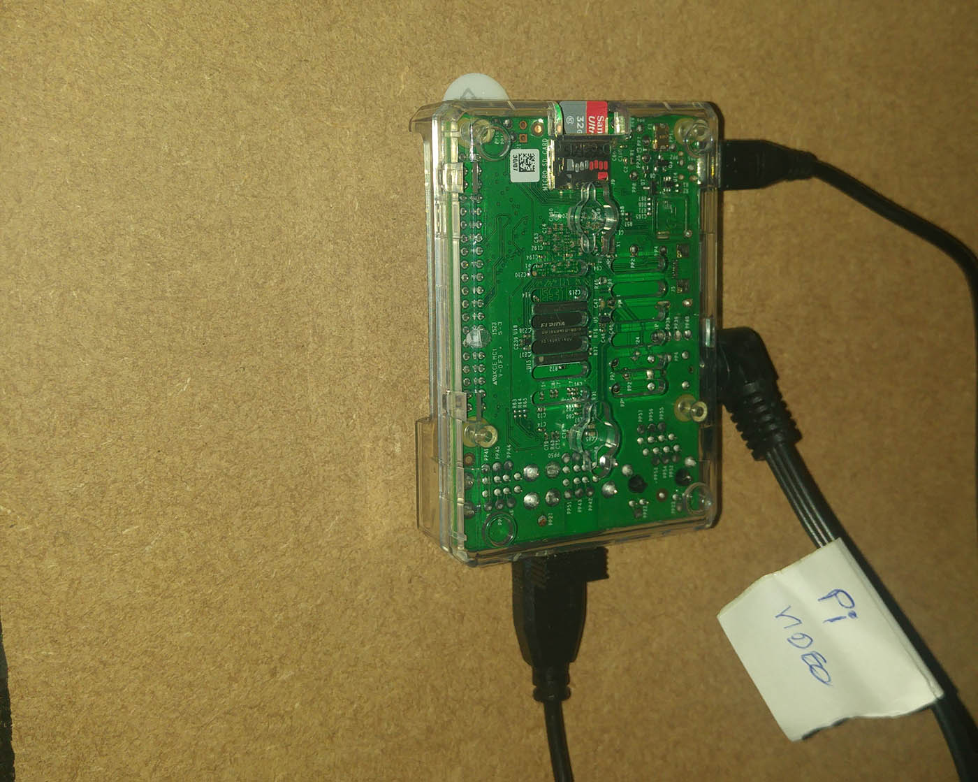
Raspberry Pi
I didn’t want the Raspberry Pi just hanging in mid-air though so my solution for it was to use some velcro. I got a case with it when I got the Pi and I used a couple of those sticky velcro picture hanging pads to stick the Pi to the inside cabinet wall. I made sure it was within arm’s reach of one of the coin doors so I could take it out if required. The Pi takes inputs of power through Micro USB and also the controller board through USB. The output is video and audio via it’s dual purpose jack. I got one of those camcorder style composite RGB cables which has the right-angled jack end at one end which goes into the Pi and the red, white and yellow composite ends on the other end. The red and white ended up going to the amplifier for the speakers and the yellow went to a SCART adapter and into the back of the TV. Be careful when buying your composite cable here as not all are compatible with the Pi. The Pi website has further details and I think I actually bought mine from the Pi store so that I knew it would definitely work.
Television
I already spoke in the previous post about The TV Monitor about the issues I had to consider regarding the TV. I had to make sure the TV would switch on when I plugged the whole cabinet in and wouldn’t need a physical push of a button on the unit, and also I got my neighbour’s help in making it always switch onto the AV channel automatically by means of an extra power supply which switches the SCART connector to a different pin.
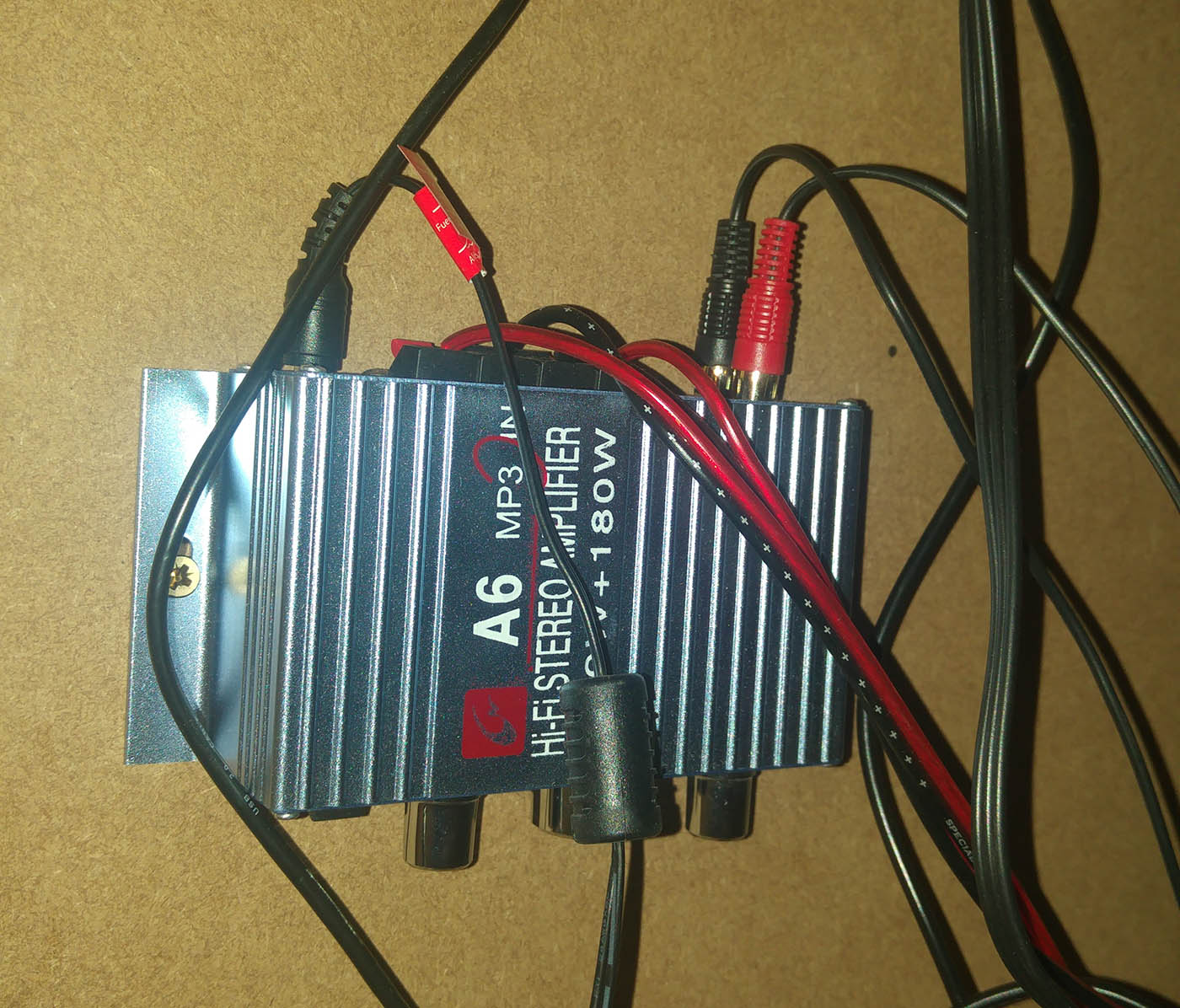
Speakers and Amplifier
I had bought a speaker and amplifier pack from, you guessed it, Arcade World UK, and these were really easy to install. I just had to make sure the wires were long enough to reach all the way down the cabinet as I screwed the amplifier onto the inside of the cabinet near the bottom and the speakers are obviously up near the top. I wanted to be able to reach inside using the coin door in order to adjust the volume.
Marquee Light
I had to look for a little while to find a strip light that was right for my needs actually. In the end I found one in a local hardware store. I went for an LED wardrobe light, even though it was a bit more expensive, as the LEDs wouldn’t heat up. If I can minimise the chance of starting a fire then I will. It’s worth an extra £5. This light was easy to attach to the underside of the cabinet top. I just put it about halfway or actually slightly nearer the front perhaps. Some people put tin foil around the inside of that area to help bounce the light but I found that the light was bright enough without having to do that. Again this was just left in the On position so that when the main plug was plugged in it would switch on automatically.

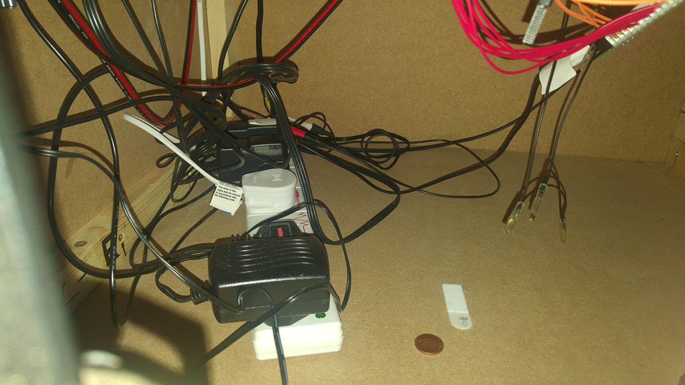
Power strip
So you can probably work out that I had 5 plugs required. The Pi, the amp, the light, the TV and the SCART switcher. I had got a 6 plug extension lead and used some more sticky velcro pads to attach this to the base of the cabinet. I had just cut a small indent in the back of the cabinet panel in order to let this cable stick out the back. I actually cut the whole too big which was a bit annoying. I’ll plug it up with something at some point. Some people put nice big power switches on the back or side of their machine to power up their machine easily, but I wasn’t confident to mess about with that sort of thing though so I kept it simple and just made it that it all switches on when you plug the main power lead into the mains. For powering down, I just Quit the Retropie software and then switch the power off at the mains.
So now we have everything wired up and working, it’s time to install the software and play some games!
Here’s a list of all the posts about my arcade build.
Part 1
Part 2 – Decisions
Part 3 – Cabinet Design
Part 4 – Control Panel Plans
Part 5 – Initial Questions and Concerns
Part 6 – Online Resources
Part 7 – Cabinet Plans
Part 8 – Buying and Cutting the Wood
Part 9 – Tools and Materials
Part 10 – Building the Cabinet
Part 11 – Building the Control Panel
Part 12 – Sanding and Painting
Part 13 – The Coin Door
Part 14 – Artwork
Part 15 – Printing and Applying the Vinyl
Part 16 – Adding all the T-moulding
Part 17 – The TV Monitor
Part 18 – Making the Bezel
Part 19 – The Marquee
Part 20 – Installing the Electronics
Part 21 – Setting up MAME
Part 22 – Issues to Watch Out For
Part 23 – The Finished Cabinet
Matt Porter
May 16, 2022 -
They have hooking up Burger King cabinet night before they’re sitting Oklahoma need help thank you sorry about the phone sitting in Oklahoma 736-64 send instructions please
How to Game on a Budget | Retromash
Jul 26, 2024 -
[…] willing to delve into the world of emulation, there are numerous options to explore. Devices like Raspberry Pis, Anbernic handhelds, and the Mister FPGA allow gamers to emulate a wide range of consoles and […]